In order to keep your Boiler running safely at peak efficiency it is important to observe proper maintenance. We have provided the following maintenance articles to assist you towards that end.
Download PDF Version
12 Ways To Avoid Boiler Tube Corrosion
By: H. F. Hinst
Plant Metallurgist
Tubular Products Division, Keystone Plant
The Babcock & Wilcox Company
Corrosion troubles in low pressure heating boilers — which usually operate at a steam pressure
below 15 psig or water pressures below 30 psig and are often of the horizontal fire tube type —
often occur unnecessarily.
During the past 60 years we have had many occasions to examine boiler tubes to
determine the reason for their failure. In very few cases have any defective qualities in the tubing
been the cause of the corrosion. In the vast majority of instances, the necessity for replacement
has been traced to conditions of environment.
In power boilers, it is a rare occurrence to find corrosion of the type common to heating
boilers. This is because operators of power boilers realize the importance of proper water and fire
side conditions and take care to avoid such problems.
The users of heating boilers are, first of all, usually not aware of the possibilities of
corrosion. Often they have little idea what causes it and lack the know-how and experience to
combat it. Fortunately, scale is not a major factor in low pressure boilers, although a buildup of
scale at tube ends has occasionally resulted in failure by grooving next to the tube sheet.
Let us first consider the various mechanisms which lead to pitting or water side corrosion
since this is the most common type. This accounts for 75 percent of the tubes examined in our
laboratory.
Steel does not corrode appreciably in dry air, but only in the presence of moisture.
Likewise, steel will not corrode in clean, alkaline, freshly-boiled water, if air is kept away.
This has been proven to our satisfaction by placing samples of tubes in ordinary tap water
in flasks and boiling the water, causing the steam to condense and run back into the flask. When
we allowed the condensed drops of water to be free to contact the air, corrosion of the tubes took
place. When we took the oxygen out of the air in the flask and condenser by running the air
through pyrogallic acid (which is an oxygen-absorbing liquid), no corrosion of the tubes took
place.
Oxygen and Velocity Factors
This proves that the presence of oxygen is an important factor in corrosion problems. It
was also found that if the heaters were shut down at night, the corrosion was much more rapid
than if the apparatus were kept boiling. In effect, some of the oxygen was excluded from the flask
by the steam space over the boiling water. In low pressure heating boilers, however, the return
water usually enters at the bottom, which does not afford the oxygen reduction which would be
obtained if it would drop through the steam space.
Pitting is probably the most destructive form of corrosion that affects the water side of
boiler tubes. Frequently, only a few pits are present and most of the surface is unattacked. In
other cases, the pits cover most of the surface, and as a further extreme, the pits all run together
and the corrosion takes the form of uniform attack. The frequency of the pits is determined to a
large extent by the degree of acidity or alkalinity of the water.
Acidity and alkalinity are dependent upon the amount of hydrogen-ion concentration
found in the water. Both would be expressed in terms of the pH scale. A strong acid solution —
strong muriatic or sulfuric acid — is rated as 1; a strong alkaline solution — concentrated caustic
soda — is rated as 14. A neutral water has a pH value of 7.
Below a pH of 5, the water is actually sufficiently acid to dissolve the steel, and under
these conditions no pits form. Instead, the corrosion is relatively uniform and the steel gradually
gets thinner until it is too weak to hold the pressure, or a small hole develops.
Between a pH 5 and 9.4, pitting takes place at a rate depending on the concentration of
oxygen in the water. Therefore, while operating the boiler, it is necessary that all air or as much
air as possible be excluded from the boiler water.
it has been shown that a strip of steel hung in the middle of a fast moving stream did not
rust, while an identical piece hung in a stagnant pool along the edge of the same stream pitted
badly when connected to the first by a wire. This proves that velocity and air content have an
effect on the corrosion of steel. In most cases, the pitting in horizontal fire tube boilers takes
place along the top of the tubes on the outside, and it is our belief that this may in part be due to
the difference in velocity of the rising water and steam bubbles, creating an eddy effect along the
top of the tube and accelerating the corrosion, much as did the experiment of the flowing stream.
In any event, pitting would not occur in this type of boiler if no oxygen were present in the water.
Practically all ground surface supplies of water contain dissolved air in quantities depending on its source, time of exposure and its temperature. Cold water will retain more airthan warm water, as can be seen by filling a clear bottle with cold water from a tap and allowingit to stand overnight. Small air bubbles will form on the sides, demonstrating that as the waterwarms up the gas is liberated.
This release of the air in the form of bubbles creates a problem in a newly filled boiler. In
a new boiler, or in one which has been drained and refilled with cold water, as the water warms
up, air bubbles form on the tubes. In a very short time pits develop under these bubbles, due to
the difference in oxygen concentration under the bubbles and the oxygen concentration in the
water surrounding the bubbles. Penetration as high as 50 percent of the tube wall has been
known to take place in one stagnant period of two weeks duration. Once these pits form, they
proceed rapidly even under operating conditions.
Why New Tubes Corrode
Sometimes a set of new tubes installed in a boiler has been found to last less than a year,
whereas the former tubes lasted five to ten years. Obviously, something has changed. Often the
tubes are blamed for the failure, when actually there have been changes associated with the
operation and maintenance of the boiler. A different method of starting up may have been used.
Circumstances may have been such that the boiler was immediately fired when the old set of
tubes were put in, while the new set may have been exposed to the fresh water for some time and
air bubble pitting may have started, leading to the eventual failure of the tubes. The temperature
of the fill-up water may have been different; and, therefore, more air was present in the new
installation. The composition of the fill-up water may have changed; a thin scale may have been
laid down at the beginning of the life of the old tubes, which served as a protection. Changes in
electrical connections may have induced stray currents, leading to possible electrolytic corrosion.
Small air or steam leaks around pipe joints and valves may have let air into the new setup. Air
vents may have become plugged due to jarring of the piping. In short, any number of things may
have happened and caused the failure.
A large number of boiler tube failures take place in the fall when starting up for winter
operation. These are due to both the air bubble pitting previously mentioned, and to oxygen
sucked into the system through packing and other sources.
Remove Air From Water
The bottle test shows that air can be removed by heating both the fill-up water and the
regular feed water. After every filling, a steam boiler should be heated to bring the water to a
good boil and the steam so produced should be vented off to carry the released gases out of the
boiler. Before this boil out, water treating chemicals should be added so as to get good mixing.
After the boil-out, the vents should be closed and the boiler used or cooled down if not needed.
In hot water systems, production of steam is not desirable, so the water temperature
should be raised to 180° to 200° F for a short time to allow most of the air to be driven off
through vents.
In larger boiler installations, air is removed from the feed water by heating it to the
boiling point and venting off the dissolved gases. In small installations, this is hardly practical.
However, in steam systems requiring large quantities of make-up water, it may be
possible to fit the return condensate tank with a steam coil to preheat the water to near the boiling
point. This tank would have to be vented to release the gases.
Another method suggested by F. N. Speller, a noted authority on corrosion, is to pass the
feed water through a de-activator, which is a tank containing steel scrap, such as turnings or
wires. The oxygen in the water attacks the steel in the tank so that corrosion properties are
neutralized. The process is satisfactory if the tank is big enough to permit complete de-activation
and if the scrap steel is renewed often enough. The practice is not frequently followed in steel
heating boiler installations because other methods of control are usually more desirable.
In addition to the air carried in by make-up water, substantial quantities may be pulled
into the system during operation by the vacuum in the condensate line, or by the vacuum formed
when the boiler is shut down or the fire is allowed to die off. In small heating boilers, warm days
during spring and fall and even in the winter often result in cooling down a boiler and radiators.
Condensing steam creates a vacuum which pulls air into the system through leaking pipe
connections, traps, vents, valves and packing. Proper maintenance of the entire heating system is
a must.
Hot water systems should not suffer from air entering with make-up water because makeup water should not be required. We say should, but there are cases when it is required because cleaning people are drawing off hot water, garage men are washing cars with it, circulating pumps leak, floats become water-logged or automatic feed systems stick.
Systems are sometimes designed to be pressurized with compressed air in such a way that
a large area of water is exposed, allowing dissolving of air to take place. We have seen systems
where well water was pumped into a horizontal cylindrical tank which was pressurized with air
across its whole surface. Another system had hot water from three boilers pumped to an
overhead horizontal tank of about 5,000 gallons capacity, which was pressurized with
compressed air from a pump in another building. No one had any idea of how much air was
being pumped into this system. Eighty pounds of sodium sulfite (an oxygen scavenger) added
per day to this system could not keep up with the dissolved oxygen being pumped into it.
Any pressurizing of this type should be in an offshoot of the system, not in the main
stream. If it must be in the main stream, nitrogen gas should be used for pressurizing.
Obviously, there are many ways air can get into boiler water; it’s difficult to keep it out.
Fortunately, however, there are methods for rendering it inactive.
How To Remove Oxygen
One method of removing oxygen from boiler water is through the use of an oxygenabsorbing chemical such as sodium sulfite. If only small quantities of oxygen are present, the addition of this chemical is practical. It is impractical, however, to try to remove large amounts of oxygen by using this chemical in large quantities, because constant additions would cause foaming. Control of alkalinity of the water must be maintained in conjunction with the use of sodium sulfite. The pH should be 9.5 or higher. Hydrazine is a chemical frequently used in large utility boilers to remove dissolved oxygen. However, it is not recommended for heating boilers because it must be closely controlled. Very seldom is such chemical control available in these installations.
Inhibitors are a class of chemicals which deposit a coating on the surface of the steel or react with it in some way to protect it against attack. These inhibitors, usually composed mainly of sodium chromate, are available from most water treating companies. When added to the water in the recommended quantities, they will protect the boiler surfaces during either operations or standby. Since they are harmful if taken internally, and may stain other products, they should not be used wherever the steam is to be used for process work. These compounds have the advantage of imparting a yellow color in the water, which the boiler user can see in the gage
glass, and thus readily determine if more is needed.
Some trouble has been experienced from use of these compounds in hot water systems
due to the formation of sodium chromate crystals in pump seals, resulting in leakage.
Concentrations lower than the 2.2 pounds per 100 gallons recommended for steam boilers have
been suggested for hot water boilers.
The value of this compound, and of another inhibitor containing sodium nitrite and
sodium nitrate, was established in a series of tests performed at the Babcock & Wilcox Research
& Development Center. These tests proved that both the sodium chromate and the sodium
nitrite-nitrate inhibitor were effective not only in preventing attack by dissolved oxygen, but also
in stopping further attack after it had started. There are some limitations on the amount of
chlorides or sulfates that can be tolerated, but these are seldom a factor in waters used in heating
boilers.
A few years ago, there was a flurry of “gadget” type water conditioning cure-alls being
offered. One such device, designed to fit into a supply line, was purchased and tested. It proved
ineffective in either preventing or stopping corrosion of the tubes.
Don’t Drain Chemical
Many boiler owners completely drain their boilers once or twice a season under a
mistaken belief that the water in the boiler is dirty. Actually, this practice, and the practice of
periodically draining small quantities of water from the boiler, should be discouraged. It causes
loss of chemicals and requires make-up water, which brings in more oxygen. However, if
additional chemicals are added each time to compensate for losses, little harm will be done.
Insurance companies require periodic tests of the low water cut-off, and at such time protection
should be insured by the addition of such chemicals.
Instead of inhibitors, alkalizers such as caustic soda may be used. It is recommended that
2 oz. of caustic soda per 100 gal. of boiler water be added at the time of a fill up. This will insure
a pH of 11 to 11.5, which will greatly reduce the pitting effect of dissolved oxygen. Some prefer
a lower concentration, down as low as 1.3 oz. per 100 gal.; but, except for the possibility of
foaming, the larger quantities can do little harm, and act as a safety factor should losses take
place by draining. However, alkalizers will not stop pitting once it has started.
In new boilers, or in old boilers which have been retubed, a boiling out using cleaning
compounds is suggested. This is necessary to remove oils and other coatings put on the tubes by
the manufacturer prior to shipment or storage. These materials are put on the tubes to protect
them from rusting during storage and transit, and have no place in a boiler. Since they may
shield portions of the tube from direct contact with the water, pitting may be accelerated. A good
boil-out is recommended, using a cleaning compound such as one of the newer detergents, or a
mixture of 2-1/2 lb. of caustic soda and 2-1/2 lb. of soda ash per 100 gal. of boiler water.
Fire Side Corrosion
Approximately 15 percent of the tubes we have examined have failed by fire side attack.
Corrosion on the fire side of boiler tubes is caused by moisture condensing from the atmosphere
during periods of shutdown, or from flue gas condensation during operation. This type of
corrosion is especially troublesome in boiler installations near bodies of water, or where the
atmosphere is otherwise humid. Fire side corrosion is accelerated by the use of high sulfur fuels.
Sulfur gases may condense on tube surfaces during operation; depending upon the kind of fuel,
its sulfur content and the methods of firing.
Accumulations of soot on the tubes should be periodically removed. Soot attracts
moisture; and air, moisture and steel together result in attack of the tubes. Cleaning may be
daily, weekly or monthly, depending on the fuel used and the method of firing.
Some hot water boilers — for example, those in greenhouses — may operate at water
temperatures of 140oF to 150oF.
Under such conditions, the condensing gases from coal or oil firing form sulfurous acid which attacks the tubes and results in a more uniform type of corrosion. If the percentage of sulfur in the fuel is high, this situation is worse. Even in the absence of sulfur compounds, corrosion may occur during shutdown periods because of high humidity in the air. When shutting down the boiler under such conditions, the fire side tube
surfaces should be brushed and flushed to remove the winter’s accumulation of soot and other
products of combustion. This should be followed by blowing air through to dry out these
surfaces. A light coat of oil should be applied for further protection. Also, in extremely humid
locations, the stack should be disconnected, or at least the damper should be closed, and a tray of
unslaked lime placed in the ash pit to keep the fire side dry. This lime must be renewed
whenever it becomes mushy, so the drying effectiveness will not be lost.
Many samples of scale removed from fire side surfaces have been found to be acid when
mixed with water. The presence of this acid may cause the tube metal to eat away to eventual
failure.
Often, boiler rooms are in damp cellars, some with water on the floor constantly. During
the summer months, in particular, humid air tends to build up in basements, causing clothes and
leather to mildew from the dampness. Similarly, humid air may have ready access to the fire side
of boiler tubes in basement installations if the tubes are not properly protected.
Even with gas firing of hot water boilers, serious fire side attack can take place. Some
installations employ outdoor-indoor thermometers to control system water temperatures as
outdoor temperatures fluctuate. Low water temperatures can result in condensation of moisture
from the flue gas and lead to serious corrosion of the tubes. High water temperatures reduce the
probability of attack.
Some horizontal tube boilers suffer from a mechanism called “necking” and “grooving.”
This shows up as a circumferential groove around the outside of the tube where it enters the tube
sheet. It usually occurs at the beginning of the first pass, which is the hottest end of the tubes. In
all cases, there is some corrosion in evidence in other areas, but it concentrates at the ends
because of strains from two sources. When tubes are rolled in, some unavoidable expansion
takes place back of the tube sheet. Secondly, when a boiler heats up, the metal in the tubes
expands and lengthens. Consequently, strains are set up at the ends, which are fixed in the tube
sheets. Sometimes these expansions are so severe that the tubes loosen in the sheets. Scale
forming at the tube ends tends to flake off, exposing fresh steel to further attack. This problem
can be reduced by more gradual firing, more gradual changes in temperature, and maintaining the
boiler water free of oxygen and under proper control.
Following the precautions and controls described in this article should result in many
years of trouble-free, economical operation.
Follow These Rules
Out-of-Service Factors
1. Boil out the boiler with an alkaline cleaner after installing new tubes to remove oil or
other coatings from the tube surfaces. These protective coatings are commonly applied to
new tubes to prevent rusting during storage and transit, and will cause corrosion if left on
the tubes during operation of the boiler.
2 Bring a steam boiler to a good steam output as soon as it is filled to deaerate the water.
Heat the water in a hot water boiler to 180oF for the same reason. A temperature of 180oF will not remove all the air, but the majority will be driven off.
3. Add sodium chromate or sodium nitrite – nitrate inhibitors to the water in the quantities
recommended.
4. In greenhouses or in damp locations, put a tray of unslaked lime in the ash pit to absorb
moisture, and close the boiler. Inspect this lime occasionally and renew when it becomes
mushy. In-Service Factors 1. Keep all boiler and system fittings airtight.
2. Add sodium chromate or sodium nitrite – nitrate inhibitors to the water in the quantities
recommended.
3. Preferably, use a fuel with low sulfur content to avoid the corrosive action of sulfur gases.
4. Brush, flush and dry out the insides of fire tubes as often as possible to remove soot and
other products of combustion, and to prevent the accumulation of moisture and
condensed sulfur gases.
5. Use sodium sulfite regularly in the boiler feed water to remove dissolved oxygen.
6. Use suitable feed water heater or deaerator to reduce the oxygen content of the boiler feed
water.
7. Prevent water leakage and avoid draining water from the system. Addition of make-up
water results in loss and dilution of the treatment, and introduces air into the system.
8. Don’t pressurize a hot water system with compressed air over large areas of water.
Download PDF Version
Safer maintenance of steel heating boilers
A modest investment in a sound maintenance program for steel heating boilers can return dividends to both owners and operators.
For owners this can mean less expenditures for repairs, more efficient operations, and longer life for the equipment. Most of all, a planned program, properly executed, can reduce the likelihood of an accident capable of curtailing production or even closing down the plant.
For operators, maintenance results in safer operations — reason enough to adopt the program — and a generally improved working schedule. Many minor difficulties that frequently lead to major problems can be avoided.
General characteristics
Most steel heating boilers possess characteristics similar enough to afford a general discussion of maintenance practices in a single article. However, some belong to service or size categories that require special maintenance–for example, very large fire tube and water tube boilers–and can therefore be included here only as general practices apply. For the most part this article is concerned with steel boilers in moderate size factories, schools, and office buildings.
Any discussion of heating boiler maintenance is incomplete if connected equipment is not included, especially closely associated major equipment such as the heating system. Accident reports show that boilers often become victims of troubles originating somewhere else. No amount of care of boilers alone can prevent such accidents.
Most service and maintenance should be performed during idle seasons, when equipment is available for examination, testing and repair; some must be completed immediately following in-service testing that discloses defects.
Cleaning practices
Some owners and operators of boilers are of the opinion that cleaning of the external and internal surfaces of the boiler may be accomplished anytime during the idle season. Therefore, the boiler receives little or no attention while it is out of use, and cleaning is virtually forgotten until just prior to the heating season.
To be most beneficial and to keep corrosion at a minimum it is important that all cleaning be performed at the start of the idle period. By so doing the working life of the equipment can be extended. Preparation for the idle season should first include proper cleaning of the boiler. External cleaning should receive priority.
As soon as possible after the close of the heating season, soot and ashes should be removed from the fire side surfaces of the boiler. Otherwise, moisture from the atmosphere or from a leak in the boiler may combine with chemicals, especially sulphur compounds from the fuel, to form an acid that will quickly corrode the boiler plates. Damp ashes behind furnace brickwork should be given special attention. Moist soot in chimney connections and fire tubes poses a threat to the serviceability of metal that was already relatively thin when it was new. External cleaning must be prompt and thorough.
Internal cleaning, by comparison, usually requires little effort. Heating boilers use only small amounts of makeup water and little scale is produced. However, these boilers often are found to contain deposits of sediment, largely rust from the heating system, that may become troublesome if left inside. It can form dams that will create puddles in hard-to-see parts of water legs. This moisture promotes corrosion, To do a necessarily thorough job of cleaning, all washout plugs and hand hole or manhole plates should be removed.
In addition, certain attachments to boilers are likely to collect deposits that must be removed periodically. Connecting lines for water columns, low-water fuel supply cutouts, and emergency water feeders — including the chambers for the cutouts and the feeders — at times become clogged. The clean-out plugs in the connecting line fittings should be removed and the chambers should be opened. After the lines and chambers are cleaned they should be left open if an internal inspection of the boiler is scheduled during the idle season.
Idle season lay-up
Two methods, the dry and the wet for storing a boiler during extended idle periods are recognized. The advantages or disadvantages of each depend somewhat on the boiler size, type, kind of service, and length of idle season.
If the idle season is two or three months long, users of most steel heating boilers prefer the dry method. It entails little effort. It keeps the boiler prepared for inspection by the authorized inspector; and it prevents internal corrosion reasonably well in most instances.
After the cleaning and inspection is finished, the boiler is prepared further by blotting, sponging, siphoning, or otherwise removing all collections of water from the bottom of water legs and other low places. A vent opening for air circulation should be provided in or near the top of the shell, even if the removal of a safety valve or other connection becomes necessary.
Usually, the foregoing meets the needs of small boilers, those that are too small for manholes, but forced drying with heat often is recommended. Only an experienced engineer should consider such an undertaking.
After the drying operation is completed, a drying agent may be placed inside, and the boiler may be closed. Two pounds of quick lime, ten pounds of silica gel, or the equivalent of some other desiccant, for each thousand gallons of boiler water capacity will suffice in most instances.
The wet method has at least one advantage over the dry method of storage: the boiler requires little preparation for service, and therefore it may be fired soon after it is needed. When cleaning and inspection are completed, the boiler is closed and is filled to the top with water that has been treated to prevent corrosion.
Owners of small heating plants are advised to get instructions from a qualified boiler water chemist if the wet method of storage is used. If corrosion is to be controlled, proper lay-up procedures must be observed.
While in storage by either the dry or the wet method, a boiler should be treated with reasonable care. The furnace must never be used as a receptacle for trash, especially not if it is to serve later as an incinerator for the collected trash. To prevent such abuse by others, the person in charge should either fasten a warning sign to the firing door or should place a lock on the boiler room door, or both. To avoid almost certain damage that would result from firing an empty boiler, appropriate fuses in the firing system should be removed or other means should be adopted for keeping the unwitting or would-be operator from firing the boiler.
Maintenance and service
As soon as possible after the boiler has been prepared for an idle period, attention should be directed toward the heating system and associated equipment. The kind and extent of the service effort to be applied is frequently determined by experience — the type of experience, unfortunately, that makes itself known most forcefully via boiler accidents.
The type of boiler accident known as a low water accident occurs if the fuel continues to burn in the furnace of the boiler when the boiler water level falls below the minimum safe point of operation. From a frequency point of view it outstrips all other types of boiler accidents. Usually, heating boilers require little makeup water. This means that most such accidents happen because something stops the supply of return water.
Condensate return pumps, though not the greatest source of trouble, fail in service for many reasons, resulting in low water accidents. Pumps fail to deliver water when they become steam bound or when bearings burn out. and moving parts in time become so worn that the pump can no longer carry its load. At times, moreover, the pumps and return lines freeze during cold snaps only because those in charge forgot to replace nearby broken windows.
The piping and other parts of the connected heating system cause return water losses for reasons less subtle than wintertime freezing. Usually piping corrodes internally. Sometimes it makes its presence known by causing minor leakage at some threaded joint in an open place, where fortunately it may be found before some form of water damage results or a low water accident happens. When the steam fitter makes the repair, he often finds that all adjacent piping requires replacement. Internal corrosion penetrates the pipe wall and corrosion products clog pipes and fittings. In time, these products can be expected to interrupt the return flow of condensate. Also, if either the supply or return piping passes unprotected through coal bins or underground, failure from external corrosion will occur eventually.
Traps in heating systems also contribute to water loss difficulties. Defective traps pass steam to the return system, and the steam escapes through the vent on the condensate return tank. Steam in this tank may also heat the condensate enough to cause steam binding of the return pump. If the emergency water feeder should fail (it often does through lack of use), or if the boiler has no emergency water feeder, the steam loss might well result in a deficiency of boiler water.
Defective vents on the piping, especially those installed in isolated places, also may waste steam in amounts large enough to lower the boiler water level in time.
Expansion tanks on hot water heating systems require periodic attention too. At least once a year, preferably before the start of each heating season, they should be drained. Otherwise, they may become waterlogged and cause the water relief valves on the boilers to discharge each time the water undergoes thermal expansion. The cause of such a discharge has been misunderstood occasionally and has induced uninformed operators to tighten relief valve springs or to plug discharge ends of escape pipes, an obviously dangerous “cure”.
The firing system, particularly the burner for the boiler, is another part that must have attention, and many users contract with service organizations to check and maintain it. Failure to keep it in order may result in loss of heat during a cold period or, worse still, in a furnace explosion as a result of a delayed ignition of accumulated fuel.
If the fuel is gas or oil, a few general remarks on common faults found during inspections will indicate what to expect. Ignition electrodes may burn, become coated, or become displaced. Ignition transformers may deteriorate or fail completely. Fuel lines leak,. fuel strainers become stopped, and fuel valves leak or fail to close when dirt lodges between discs and seats. Air-fuel ratios drift until the flames stifle when someone closes the last open window or door to the boiler room, thus eliminating needed combustion air. Many owners and operators have learned too late that a permanent opening to the outside is required and must be installed so that it won’t cause wintertime freezing of condensate return lines.
Fast-acting, modern flame-failure safety devices serve a definite purpose. No one can estimate how rapidly boiler accident frequency would increase without them. But like all safety devices, combustion safeguards are not foolproof. Not only are the electronic parts themselves certain to fail now and then, but non-electronic parts–valves, burners, pressure regulators, piping–if neglected, are sure to produce accidents and outages at least occasionally.
Safety devices of all kinds require attention. Safety valves head the list of such devices that must be kept in working order. In recent years inspectors have traced the causes of a number of boiler explosions, some that have injured and killed, to valves with moving parts that had “frozen” in place from neglect and disuse.
Section VII of the ASME Boiler and Pressure Vessel Code proposes a way to avoid such troubles with safety valves on lower pressure power boilers. It suggests that the boiler pressure be raised high enough at least once a year to pop each valve. It further suggests that the safety valve disc be raised to the full open position several times a year by using the lift lever.
Safety valves on heating boilers deserve no less care. A pre-season popping-pressure test and a monthly lift-lever test seem little enough effort to expend on such a vital device. Give it a full popping-pressure blow before the heating season starts; also, raise the boiler pressure to within five psi of the popping-pressure and pull the lift lever until the valve opens fully. This should be done no less than once a month throughout the heating season.
Low-water fuel supply cutouts, and the lines connecting them to boilers, follow safety valves in importance only because low water accidents, the kind the cutouts should prevent, kill or injure fewer people than do boiler explosions.
As a defense against these forms of distress, low-water fuel supply cutouts on steam heating boilers (they serve as well on hot water heating boilers, if maintained) stop burners or fuel flow when the boiler water level falls too far. They do, that is, when kept up, but they have many parts that otherwise can and often do fail either electrically or mechanically.
Tests to detect these faults merit a place in the boiler service schedule. A real test of a low water cutout takes but little of the operator’s time. Reasonably often, say once a month, he must remain on constant watch while, by some convenient means. the boiler water level is lowered slowly until the burner stops, or until it should but doesn’t stop. If it does stop when the water level reaches the cutout set point, the cutout may be regarded as having passed the test, and the boiler may be filled and otherwise prepared so that it will resume normal service. But if the cutout doesn’t stop the burner, the cause of failure must be found and corrected without delay.
The low-water fuel supply cutout also requires regular service during both the heating and the idle seasons. Once a week while the boiler is under pressure, the operator should flush the float chamber (if the cutout is a chamber type) thoroughly enough to remove collected sediment. Naturally, the blow down valve must be opened wide enough to flush all the water from the chamber and to extinguish the fire. If it doesn’t extinguish the fire the cutout should be tested and, if necessary, repaired. Like other parts of control and safety systems for modern, automatically fired boilers, cutouts might well be too complex for most boiler operators to service. The need for thorough service by an experienced serviceman can’t be over-stressed.
Most frequent type of accident is burning and not explosion
| Fire Tube Boilers | Water Tube Boileer | Cast Iron Boilers | ||
| Type of Accident Percent | Type of Accident | Percent | Type of Accident | Percent |
|
Tearing Asunder 19.0% (Explosion, Rupture) |
Tearing Asunder (Explosion, Rupture) |
50.0% |
Tearing Asunder
|
5.9% |
| Crushing (Collapse) 5.0% | ||||
| Burning 70.0% (Overheating) | Burning 46.0% (Overheating) | Burning 70.0% (Overheating) | ||
| Bulging 2.5% | Bulging 2.5% | |||
| Cracking 3.5% | Cracking 1.0% | Cracking 92.4% | ||
| 100.0% | 100.0% | 100.0% | ||
Contrary to common belief, the most frequent type of accident to heating and power boilers is not explosion.
Although explosions are an ever-present threat to operation, the most frequent type of accident is burning, that is, overheating because of a deficiency of water.
Burning not only accounts for the largest number of accidents but also the largest total dollars in any boiler accident classification.
This frequency table on types of accident classifications is based on an analysis of the type of accident, the specific part of the object that failed, and the primary cause of failure. It is also designed to provide statistical information to indicate the general direction toward which accident prevention efforts can best be directed.
The higher percentage of water tube boilers in the tearing asunder category, as compared to the percentage of fire tube boilers, is accounted for by the fact that most tube failures in water tube boilers are classified as tearing asunder cases even though burning (overheating) may have been a contributing factor.
The cracking category is confined to the cracking of cast metal parts. In the case of cast iron boilers, however, it is by far the most common type of occurrence. In many cases of cracking, overheating is a contributing factor although the final occurrence is cracking.
Safety check list for boilers
- Test controls and safety devices regularly. Correct any defects immediately.
- Keep controls and safety devices in proper working condition. For example, blow down the chambers of the low-water fuel supply cutout and operate the lift lever of the relief or safety valve regularly, while the boiler is in service.
- Have a reliable service organization check and service the equipment periodically, both during and between heating seasons.
- As soon as possible at the end of each heating season, drain the boiler and clean it both internally and externally. Remove all clean-out plugs. Open and clean the chamber of the low-water fuel supply cutout.
Repair furnace brickwork and lay-up the boiler.
- Examine and repair heating system components and boiler auxiliary equipment.
- Don’t leave broken windows or other openings that may permit wintertime freezing.
- Don’t block the combustion air supply opening for the fuel burning systems.
- Don’t use the boiler furnace as a trash receptacle or incinerator during the idle season.
- Don’t leave the boiler room accessible to unauthorized persons.
- Don’t leave the boiler during the idle season so that the burner can be operated in a routine way by an unqualified operator.
By W. H.. Russell, The Hartford Steam Boiler Inspection
and Insurance Co. Photos and data
courtesy of The Boiler Inspection and Insurance Co of Canada.
CPE:/ PE & M — March, 1966
Download PDF Version
INTRODUCTION:
In other than exceptional circumstances, a natural water is not suitable for boiler feeding unless it is suitably treated, since the use of an untreated water can cause foaming and priming, corrosion of the metal, and restriction of the water spaces due to scale deposition. Serious scaling may result in ultimate failures of generating tubes and distortion of the tube plates with subsequent leakage at tube joints. It also reduces the heat transfer and consequently the efficiency of the unit.
Because of the very great differences in the composition of natural water from various sources and localities, it is quite impossible to prescribe any standard form of treatment. It must normally be based on the composition of the water supply available and, where there are alternative supplies, it is usually advantageous to use the supply which is most easily treated.
The notes which follow are not intended to be instructions, but merely a guide to the treatment and control, and the boiler user is advised to adopt the service and guidance of a specialist company supplying water treatment chemicals.
TYPE OF TREATMENT:
Generally speaking, natural water can be divided into two classifications:-
- Water of Low Hardness, which contains hardness salts of calcium and magnesium in amounts up to about 150 parts per million.
- Hard Water, which may contain hardness salts in quantities up to 500 parts per million or more.
In the case of soft water, defined in Group (I), “internal treatment” will generally be satisfactory, but, as different water requires different chemicals, the specific treatment for a given installation can only be determined properly by an examination of the water supply. “Internal Treatment” comprises the addition of chemicals to the water entering the boiler and, in this case, the reactions occur in the boiler, hardness salts being precipitated as sludge which has to be removed by blowing down.
A properly balanced treatment will convert all the hardness salts into a soft, easy-flowing sludge and render the boiler water alkaline to phenolphthalein, a condition which is necessary as a protective against “on load” corrosion.
Hard water defined by Group (II) presents a more difficult problem because internal treatment may produce so much sludge in the boiler as to make its control difficult. Suspended sludge may promote foaming in the boiler and carry-over of boiler water into the steam mains and, where possible, the water should be softened before it is fed to the boilers. Choice of the process will depend on the composition of the raw water supply. In many cases, where boilers are installed in factories or institutions, etc., where the water for process or domestic supplies has to be softened, it is very probable that the treated water will be suitable for boiler feeding after the application of an internal treatment, as described for soft water in Group (I). Therefore, these notes concentrate on “internal” treatment. Internal treatment, chemicals or mixtures usually employed invariably contain some or all of the following chemicals, the purpose of which is described:
Sodium Phosphate – which precipitates calcium and magnesium hardness salts as soft calcium and magnesium phosphate.
Sodium Aluminate – used as a coagulant.
Tannins – which render the precipitates free-flowing and, by surface action on the boiler metal, act as a protection against corrosion. They also have the property of absorbing oxygen from the boiler water.
Starch – used in some cases as alternative to tannin or with tannin. It is a coagulant and has the property that it can absorb slight traces of oil which may get into the boiler water.
Alkali – usually caustic soda ash, the purpose of which is to impart alkalinity to the boiler water.
Sodium Sulphate – used when a water deficient in naturally occurring sodium sulphate, in order to provide a sodium sulphate/caustic soda minimum ratio of 2.5 for protection against caustic cracking.
CONTROL OF TREATMENT AND BOILER WATER CONDITIONS:
The normal treatment will be the continuous addition of the chemicals to the feed water in sufficient quantity to precipitate the hardness salts in the boiler water.
Correct treatment will ensure that the feed is always alkaline with a ph between 8.5 and 9.5. The quantity of chemicals to be added will be determined by simple test on the boiler water and, briefly, these tests are:
Hardness – The hardness should always be zero. Presence of hardness is an indication of scale- forming conditions and the chemical dose should be sufficient to ensure its absence.
Phosphate – The phosphate residual in the boiler water should be not normally less than 50 and not more than 100 parts per million, expressed as tri-sodium phosphate. It is the most important test for the adequacy or otherwise of the treatment, as, in the presence of a phosphate residual to the degree specified, hardness in the boiler water cannot exist.
Alkalinity – The total alkalinity of the boiler water, expressed as calcium carbonate, should not be less than 15-20% of the total dissolved solids concentration.
Total Dissolved Solids – The total dissolved solids in the boiler water, resulting from the concentration of the dissolved solids in the feedwater, plus the addition due to the treatment chemicals, should not be allowed to exceed 2,000 to 4,000 parts per million. This figure is, however, influenced by several factors, eg., water level, changes in load, and the amount and physical condition of the suspended matter in the boiler water. Experience will indicate whether it can be increased or whether it must be decreased.
Method of carrying out the tests and recommendations for the necessary apparatus will generally be provided by the supplier of the water treatment chemicals.
Blowing Down – The frequency of blowing down which is necessary to maintain the boiler reasonably clear of deposited sludge and within the concentration specified for the total dissolved solids in the boiler water will be governed by the composition of the raw water and the amount of chemicals added. Power boilers should be blown at least once per day and preferably lesser amounts twice or three times per day. To ensure the removal of the maximum amount of sludge, the blowdown valve should be opened momentarily several times with a short pause between operations, so that the disturbance in the vicinity of the blowdown outlet can die down and further sludge move into position ready to be flushed out at the next operation.
If the dissolved solids content in the feed water is high, it may be advisable to have a continuous blowdown, but, as this is not so effective in the removal of sludge, the regular operation of the intermittent blowdown cannot be eliminated.
It is also most important that the feed water regulators be blown down at least once per day to ensure that the float chambers are clear of sludge.
Heating boilers should seldom be blown down and then only on the advice of a water treatment consultant.
Sodium Sulphate/Caustic Soda Ratio:
As scale deposits, which are likely to occur in the boiler if water treatment is faulty, may cause cracking of the tube plates with possible consequent leakage at tube seats, it is good precaution to maintain the advised sodium sulphate/caustic soda ratio of 2.5 as a protection against possible intergranular cracking of the tube plate in stressed areas.
If included in the chemical mixture, it will be in correct proportion to the alkali to provide the necessary sodium sulphate/caustic soda ratio and under these conditions tests will not be required for routine control.
Idle Boilers:
If at any time a boiler is off load for more than a few days, precautions should be taken to protect it against corrosion during such periods. For an extended length of time, the boiler should be emptied, hosed out to remove sludge and then dried thoroughly. Trays of quick lime should then be placed in the drum, after which the drum should be closed up.
Alternatively, if a boiler is to be held ready for immediate use, it should be emptied and cleaned and then be filled completely with feed water which has been made alkaline by the addition of caustic soda and to which sodium sulphite to the extent of 100-150 parts per million has been added as an oxygen absorbent. Air cocks should be closed and the water tested from time to time for caustic soda and sodium sulphite residual.
Blowdown
The purpose of boiler blowdown is to regulate the amount of total solids, dissolved and suspended, contained in the boiler water. Added feedwater carries dissolved solids that are left behind in the boiler as it is evaporated. Chemicals also add to the solids concentration. Since evaporation is continuous, the accumulation is also continuous. BLOWDOWN to waste a part of the concentrated water and replacing it with feedwater is the only way the total solids concentration can be held in check.
Failure to remove sediments and sludge accumulation may result in premature boiler failure such as cracked boiler plates, low water cutoff failures or pressure controller failure.
Failure to control dissolved and suspended solids in the boiler water may result in foaming and priming. This in turn results in a wetter steam and poor fuel economy.
Steam boilers used solely for heating and where practically all of the condensate is returned to the boiler, blowdown only as often as the concentration of solids require.
Steam boilers used for process steam requiring high quantities of make-up water should be blown down as required to maintain desired chemical concentration levels and to remove precipitated sediments.
Boilersmith Ltd. boilers are supplied with three types of blowdown connections; BOTTOM BLOWDOWN, LOW WATER CUTOFF/WATER COLUMN BLOWDOWN and SURFACE BLOWDOWN.
- Bottom Blowdown and/or Drain
The bottom blowdown permits the removal of sediment and sludge accumulation from the bottom of the boiler.
If your boiler is supplied with two blowdown valves (a quick-opening and a slow-opening valve) always open the quick-opening valve first followed by the slow-opening valve. This reduces stress on the pipe and fittings.
Blowdown of Steam Boilers
- Low Water Cutoff and/or Water Column
All AF2, AF3 and CF3 Series firebox boilers are supplied with ball valves on the low-water cutoffs for blowdown purposes of these devices. In addition to removing sediment, blowing down while the burner is running ensures that the low water cutoff is functioning. The burner should shut off during the blowdown. C) Surface Blowdown
Continuous blowdown allows dissolved and suspended solids to be removed continuously near the water surface. There are three types of Surface Blowdown.
Intermittent
Blowdown manually at a pre-determined time schedule and water testing schedule. Continuous
Blowdown continuously while the boiler is steaming. A throttling valve is installed to permit a controlled flow to drain. The amount of flow is determined by periodic testing. Automatic
A solenoid valve and flow control valve are installed. Based on conductivity or the amount of boiler feed water the solenoid valve is energized.
Download PDF Version
Thermally Induced Stress Cycling (Thermal Shock) in Firetube Boilers By Geoffrey M. Halley, P.E.
The problem of thermally induced stress cycling (loosely referred to as thermal shock), has been apparent for many years, particularly in boilers installed in hot water heating systems. The term “shock” suggests a sudden impact type failure, which in the vast majority of cases is far from what actually happens. Most failures of this type occur over a period of time, sometimes as short as a few weeks, and sometimes considerably longer. Failures are typically of the metal fatigue type, and are caused by thermally induced stress cycling of the boiler structure.
Equipment manufacturers and system designers have devised many approaches over the years to combat this problem. Some have been successful to varying degrees, and some have demonstrated a lack of understanding of the failure mechanism.
Although the effects of thermally induced stress cycling can be seen in various types of boilers (e.g. firetube, cast iron sectional and watertube), this article will be limited to an explanation of the failure mechanism and preventive measures in horizontal firetube boilers of the Scotch and firebox types. Some remarkable similarities have been noted, however, between the failures in the water legs of firebox boilers and the rear sections of cast iron sectional boilers.
Data has been acquired as a result of both laboratory stress analysis and field test programs, from which it will be seen that failures are many times the result of an ongoing conflict between energy conservation requirements imposed on the control system designer, and the requirements of the boiler manufacturer to protect the structural integrity of the boiler.
In some cases, problems have been resolved simply by resetting temperature control points, while in more severe cases, extensive system modifications may be necessary in order for the goals of the control system designer and the boiler manufacturer to be met.
Thermally induced cyclic stresses are due to the resistance of the boiler structure to movement caused by thermal expansions and contractions within the boiler. The stresses occur every firing cycle (burner on – burner off), in varying magnitudes. Failures of this type may appear as leaks at the tube to tubesheet joints, cracked tubesheet ligaments, or broken stays. Obviously failures of this type, while not likely to be catastrophic in nature, can be extremely serious in terms of downtime and repair costs.
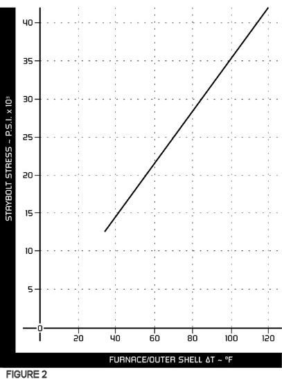
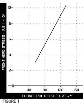
Factors Affecting the Magnitude of Thermally Induced Stresses
Scotch marine and firebox type boilers, heavily instrumented with strain gauges and thermocouples, were subjected to varying operating conditions in a laboratory environment where a simulated building heating system had been created. The findings in each case were similar, as shown in Figures 1 and 2 which show the variation of outer fiber or surface stress on a front head at the furnace/head junction of a Scotch boiler and a stay in the side water leg of a firebox boiler. It should be noted that the stresses measured are bending stresses and as such will be tensile on one side of the plate or stay. The stresses will pass through a neutral axis in the center of the plate or stay and will be compressive on the opposite side, thus mean stress is half the measured outer fiber stress. Figures 1 and 2 both show stress to be directly proportional to the mean temperature difference between the furnace and the outer shell of the boiler, thus it is purely a function of the differential expansion between the furnace and shell.
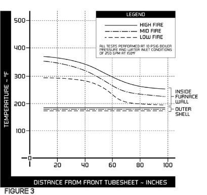
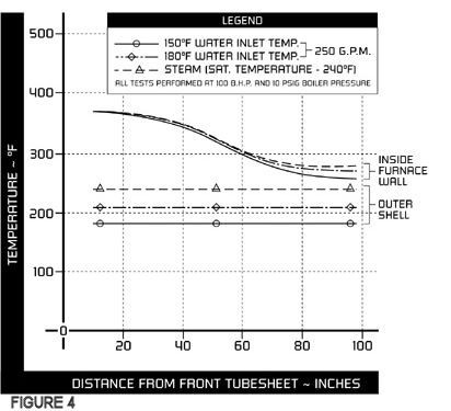
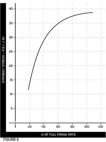
The manner in which various operating parameters affect furnace and shell metal temperatures is shown in Figures 3 and 4. Figure 3 shows how firing conditions influence the furnace metal temperatures, while Figure 4 shows how waterside conditions will affect the shell temperature. It can be deduced that a low pressure steam boiler will typically be a lower stressed boiler than the same boiler operated in a hot water system (unless of course the return water temperature is raised sufficiently to produce similar bulk water, or shell temperatures as that of a steam boiler). The effect of burner firing rate on stress level is shown in Figure 5, from which it will be seen that low fire stresses are typically 30% to 35% of the high fire stress.
Because of the fact that nucleate boiling occurs around the furnace of firetube boilers, a further factor affecting the furnace metal temperature (besides firing rate) is the boiler pressure. It is for this reason that, in high rise buildings, the boiler should either be located on the top floor of the building, or isolated from the building pressure by means of a heat exchanger.
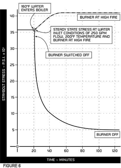
Taking the effect of furnace to shell metal temperature difference (T) on stress level to a conclusion, it would seem obvious that if the burner is not firing, then the furnace and shell should be at essentially the same temperature (T approaches zero) and the thermally induced stress will approach zero. This is demonstrated in Figure 6, in which a firebox boiler operating under steady state conditions at a 200oF water return temperature suddenly is subjected to a slug of cooler (160oF) water entering. It will be seen that the stress level on a water leg stay increases if the burner is firing, or conversely approaches zero if the burner is shut off. Obviously the cooler the water entering, the larger the increase in stress level.
To summarize the above discussion, it is known that failures due to thermally induced stresses (or thermal shock) are fatigue failures, and as such are cyclically dependent, one cycle being one on-off cycle of the burner. We also know that the stress magnitude is dependent upon the T between the furnace metal temperature and the shell metal temperature. The factors affecting furnace metal temperature are:
- Burner firing rate – higher firing rates mean higher temperatures.
- Boiler pressure – higher pressures mean higher temperatures.
The only factor affecting shell metal temperature is the bulk water temperature of the boiler. This is a function of the return water temperature and flowrate, and also burner firing rate. Obviously low bulk water temperatures mean low shell metal temperatures, and vice versa.
Field Operating Conditions
Studies into the operation of known problem installations in the field revealed the following:
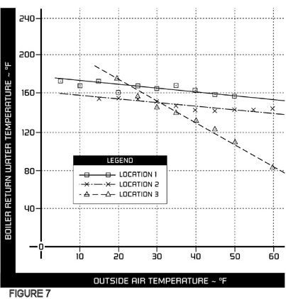
- All systems had a reset schedule on the building system temperature, based on the outdoor ambient temperature. This resulted in boiler return temperatures being lower than manufacturers’ recommendations.
Three typical examples are shown in Figure 7, from which it will be seen that return temperatures as low as 90oF were experienced in mild weather.
- Boilers were oversized for the load, especially during the mild weather of spring and fall. This resulted in cyclic operation of the boiler, one of the key ingredients for a fatigue failure.
- Burner operating and modulating controls were improperly set in relation to one another, resulting in high burner cycling rates to high firing rates. An example of this type of operation is shown in Figure 8.
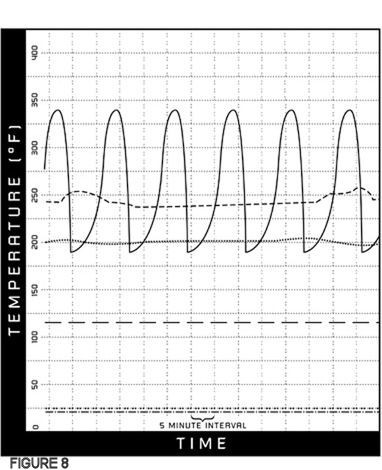
KEY
Number 2 Boiler Stack Temperature with improperly set controls
Lead Boiler Stack Temperature with properly set controls
Number 2 Boiler Outlet Water Temperature
Lead Boiler Outlet Water Temperature
Outside Air Temperature (for single boiler operation at Location 1) = 24oF
Outside Air Temperature (with lead/lag control system operating at Location 1) = 25oF
Operation of the same boiler at the same outdoor temperature, when the burner controls had been properly set, is also shown in Figure 8, from which it will be seen that cyclic operation had been eliminated for the outdoor temperature in question. Burner firing rate, and hence stress level, was also considerably reduced. In this particular case no further failures were experienced.
- Electrical load shedding is a factor to be considered in systems where air handling units are shut down for many hours allowing large volumes of water to cool down. On system restart, large volumes of relatively cold water can enter the boiler in a short period of time, unless the proper preventative measures are taken.
Protective Measures Against Thermally Induced Stress Cycling (Thermal Shock)
It may not always be possible to design a boiler structure within the confines of boiler design codes, and have thermally induced operating stresses below the fatigue limit of the steel being used. This is especially true when one considers that heating system operating parameters are most often unknown to the boiler manufacturer. It then becomes necessary for the boiler manufacturer to set guidelines for the system and controls designers to use, in order to minimize these effects.
Typically these guidelines may include:
z A minimum water return temperature to the boiler. z A minimum water flowrate through the boiler. z Recommendations as to how to set burner controls to maximize the boiler shell temperature for a given operating pressure, and minimize the number of operating cycles and the burner firing rate, for a given load condition. Prolonged periods of low firing rates is preferred to a series of on-off cycles to high firing rates.
Implementation of the Guidelines
Different boiler manufacturers may offer slightly varying guidelines as a means to over-coming the problems associated with thermally induced stress cycling. Thus, the following discussion should be taken as a generalization. Individual boiler manufacturers recommendations will override what follows.
As we have seen above, the recommendations should address the two major criteria in fatigue failures, namely reducing the magnitude of the stresses induced (reducing furnace metal temperature to shell metal temperature T) and reducing the number of stress cycles (burner firing cycles).
Reducing stress magnitude will most often be achieved by raising the temperature of the boiler shell (i.e., raising the bulk water temperature of the boiler) and attempting to isolate the boiler as much as possible from system temperature changes.
This can be achieved in two steps:
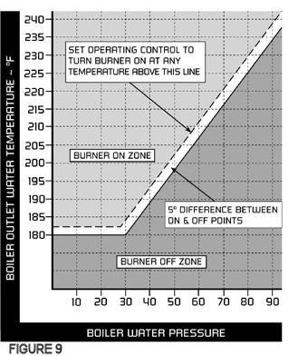
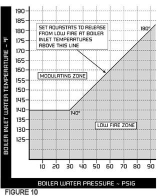
- Correctly setting the burner operating control in relationship to the boiler operating pressure, and limiting the temperature of the water returning to the boiler below which the burner would be held at low fire, to reduce stress levels. Examples of these guidelines are shown in Figures 9 and 10, respectively. It should be noted that in some systems, design or operating parameters may preclude the use of low fire hold devices, whether they be time delays or aquastats, due to the fact that the system will be unable to attain its design operating temperature without the burner being allowed to achieve higher firing rates.
- The common method of minimizing the effect of heating system temperature changes on boiler bulk water temperature is to use a two-loop system.
One loop of the two-loop system is the boiler loop, which is operated at a constant temperature set in accordance with the guidelines above. Typically, this loop would have a minimum flow requirement imposed by the boiler manufacturer. (In the absence of a detailed knowledge of system operating parameters, a rule of thumb is 0.5 to 1.0 gpm per Bhp, depending upon the boiler manufacturer.) This breaks up any tendency to temperature stratification within the boiler, as well as attempting to achieve the desired level of shell temperature.
The second loop is the building system(s) loop in which the temperature will vary in response to an outdoor temperature reset schedule, and in which flow rate may vary to meet energy conservation criteria.
The interface between these two loops is usually either a three- or four- way valve, to which the building system temperature reset schedule is applied. This allows sufficient water from the hot boiler loop to blend with the cooler water returning from the building heating system to achieve the temperature requirements prevailing at any given time. There are obviously many system configurations that will meet this basic concept.
Reducing the number of stress cycles is achieved first by correctly setting the burner operating and modulating controls in relation to one another. This means that the modulating control must not send the burner to the high fire position immediately after the operating control has initiated the firing sequence, and the main flame is established. (Reference Figure 8)
The second method of reducing the number of stress cycles is to carefully select boiler sizes and burner turndown rates (high fire fuel flow/low fire fuel flow) for a given boiler room. The heating season load profile must be matched, paying particular attention to the low load segments in the spring and fall, as it is in these periods where there will be a tendency for the boiler/burner to cycle on and off more frequently. Selecting the number and size of boilers to suit a seasonal load profile may mean that the boilers will not all be of equal size but a smaller boiler will be used in the spring and fall with larger boilers handling the high load of the winter months. Alternatively, a larger number of smaller boilers may be used with a lead/lag control system (the modular approach). Properly selecting boiler sizes for a seasonal load profile has the added benefit of energy savings in terms of reduced heat loss from the boiler shell.
It is always possible that financial constraints will preclude the ideal size selection of boilers and their numbers for a given installation, however if this is kept in mind as a goal, a better system should be the result.
Conclusion
Failures caused by what is commonly referred to as thermal shock are actually fatigue failures caused by thermally induced stress cycling. They are not an indication of boiler design or manufacturing deficiencies, as has been inferred on occasion, but are rather due to the manner in which the heating system in which they are installed has been designed, controlled or operated. In some cases a lack of knowledge may be the reason, while in others financial constraints may play a part.
Download PDF Version
Download Example Log Sheet PDF
APPENDIX H February 26, 2010
Maintenance, Testing, and Inspection Log
Steam Heating Boilers
- Fill in the name of the building, its location, boiler number, fuel type used, and the year. Name the person to be contacted in an emergency or malfunction.
- Daily Checks
- Observe water level in the water column sight glass.
- Record boiler pressure indicated by the gauge at the boiler.
- Record the flue gas temperature. (This should be done with boiler running and at pressure.)
- Weekly Checks (Record the date and time the test or check was completed.)
- Drain float chamber of the low water cutoff(s), or water column(s), while the boiler is running to determine if the control will shut down the boiler.
- Close the lower gauge gas valve, then open drain cock which is on the bottom of this valve and blow the glass clear. Close the drain cock and open lower gauge glass valve.
Water should return to the gauge glass immediately.
- Observe flame condition.
- Monthly Checks (Record the date and time the test or check was completed.) Review the condition of, check or test each item.
- Check linkages for damage or disconnection.
- Watch damper controls during operation to be sure they operate properly.
- Check combustion air supply for obstructions and adequacy of air flow.
- Inspect fuel pipe for leakage and/or damage.
- Check stop valves.
- If possible, without opening the boiler, check the refractory for cracking and deterioration.
- Check the flue-chimney breeching for signs of leakage, damage or deterioration.
- Test floor drains to sure they are draining properly.
- Test flame detection device.
- Test limit controls.
- Test operating controls.
- On relief valve lift try-lever to full open and release it to snap shut.
- Yearly (Record the date and time of the check and/or inspection.)
- Inspect and clean the fireside of the boiler. Examine all gaskets and replace as necessary.
- Inspect and clean the waterside of the boiler. Replace ALL hand hole gaskets.
- Dismantle, inspect and clean low water cutoffs, water columns and equalizing piping.
- Perform daily, weekly and monthly test noted above.
- Retain this log for at least one year.
Download PDF Version
Download Example Log Sheet PDF
APPENDIX I February 26, 2010
Maintenance, Testing, and Inspection Log
Hot Water Heating Boilers
- Fill in the name of the building, its location, boiler number, fuel type used, and the year. Name the person to be contacted in an emergency or malfunction.
- Daily Checks
- Record pressure
- Record temperature
- Record the flue gas temperature (This should be done with boiler running and at pressure.
- Weekly Checks (Record the date and time the test or check was completed.)
- Observe flame condition
- Observe circulating pumps for proper operation
- Monthly Checks (Record the date and time the test or check was completed.) Review the condition of, check or test each item. a. Test flame detection devices
- Test limit controls
- Test operating controls
- Test floor drains to be sure they are draining properly
- Check fuel piping for leakage
- If possible, without opening the boiler, check the refractory for cracking and deterioration
- Check stop valves
- Inspect check valves
- Check drain valves
- Check linkages for damage or disconnection
- Observe water level of gauge glass on expansion tank
- Check combustion air supply for obstruction and adequacy of air flow
- On relief valve lift try-lever to full open and release it to snap shut
- Test low water cutoff (if possible)
- Yearly (Record the date and time of the check and/or inspection.)
- Inspect and clean the fireside of the boiler. Examine all gaskets and replace as necessary.
- Inspect and clean the waterside of the boiler every two years. Replace ALL hand hole gaskets.
- Perform slow drain test to test low water cutoffs (with burner running)
- Dismantle, inspect and clean low water cutoffs every two years
- Perform daily, weekly and monthly tests noted above.
- Retain this log for at least two years.
Download PDF Version
Download Example Log Sheet PDF
APPENDIX J February 26, 2010
Maintenance, Testing, and Inspection Log
Process Boilers
- Fill in the name of the building, its location, boiler number, fuel type used, and the year. Name the person to be contacted in an emergency or malfunction.
- Daily Checks
- Observe operating pressures.
- Water level and general conditions. Determine the cause of unusual noises or conditions and correct.
- Test low-water cutoff, pump control and/or water feeder. See Section Three, Section Five and Section Nine.
- Blowdown boiler as required. (A COMPETENT WATER TREATMENT SPECIALIST
SHOULD BE CONSULTED REGARDING YOUR WATER TREATMENT
REQUIREMENTS AND BLOWDOWN REQUIREMENTS.)
- Test water column or water gauge glass See Section Five.
- Observe condition of flame. See Section Six: Burner Manual for information on the burner supplied.
- Check fuel oil supply.
- Observe operation of boiler feed and condensate return pumps.
- Monthly Checks (Record the date and time the test or check was completed.) Review the condition of, check or test each item.
- Safety Valve – Try Lever Test See Section Five.
- Test flame detection devices See Section Six: Burner Manual.
- Test Limit Controls See Section Five.
- Test Operating Controls.
- Check boiler room floor drains for proper functioning.
- Inspect fuel supply systems in boiler room area.
- Check conditions of fireside heating surfaces.
- Yearly (Record the data and time the test or check was completed.)
- Internal after thorough cleaning See Section Five and Section Seven.
- External inspection.
- Routine burner maintenance See Section Six: Burner Manual.
- Routine Maintenance of boiler feed and condensate pump(s).
- Routine Maintenance of combustion control equipment See Section Six: Burner Manual. f. Combustion and draft tests.
- Safety Valve Pop Test See Section Five.
- Slow drain test of low-water cutoff See Section Five.
- Inspect gas piping for proper support and tightness.
- Inspect boiler room ventilation louvers and intake.
- Retain this log for at least one year.
LINKS
For more information about our industry please visit the following links: